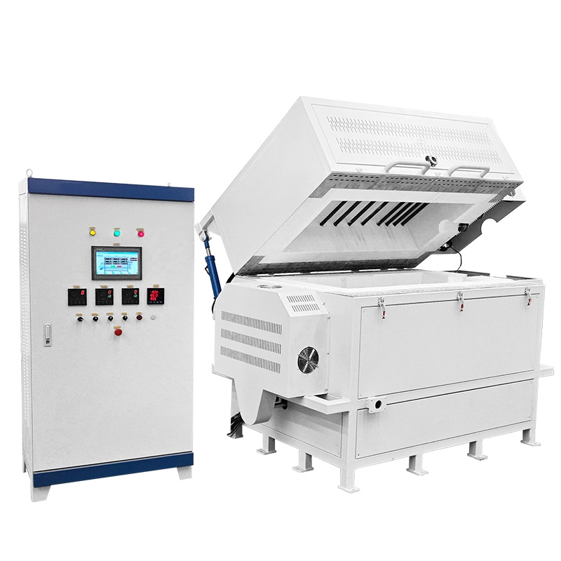
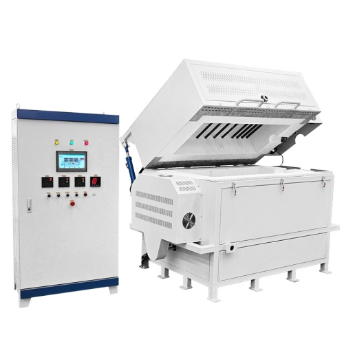

Laboratory 1300℃ Single-Tube Horizontal Purification Furnace
I. Equipment Application
Mainly used for periodic purification and sintering of silica powder at high temperatures.
II. Equipment Components and Technical Requirements
1. Equipment Schematic Diagram
(Built-in furnace tube transmission mechanism. A quartz tube is placed on the transmission mechanism. The quartz tube is wrapped with a silicon carbide/silicon nitride composite tube to prevent softening and deformation of the quartz tube at high temperatures. The transmission mechanism must be capable of carrying at least 80–100 kg. The quartz tube dimensional drawing will be provided by our company: outer diameter 300 mm, wall thickness 10 mm, length 1500 mm.)
2. Equipment Structure Standards
The main structure of the equipment includes the furnace shell structure, furnace chamber structure, furnace tube structure, silicon carbide roller transmission structure, control system, heating and temperature control system structure, and others.
Table 1. Equipment Structure Requirements
Equipment Component | Basic Requirements |
Furnace Structure | 1. The furnace shell shall have good temperature resistance, no deformation under long-term use, easy to clean, reasonable and aesthetically pleasing color matching, with no blistering or sagging of paint. |
Gas Control System | 1. The right end of the furnace core tube shall be equipped with a gas inlet pipe. The furnace tube port shall be equipped with an exhaust hood to prevent gas leakage. |
Furnace Chamber Structure | 1. The furnace lining is made of vacuum-formed high-purity alumina lightweight material. High-wear areas (furnace opening, furnace bottom) use lightweight hollow-sphere alumina board – high service temperature, low heat storage, excellent thermal shock resistance, no cracking, no spalling, good insulation. |
Furnace Tube and Roller Structure | 1. The furnace tube is a quartz tube with a cover; dimensions as per drawing. |
Rotary Transmission Structure | 1. A rotary transmission structure shall be provided on one side of the furnace body to drive the two silicon carbide rollers (both are driving rollers). The rollers rotate and drive the internal quartz tube. The transmission method shall ensure minimal radial force on the silicon carbide rollers to avoid cracking due to radial force, which would affect service life. |
Control System | 1. The temperature control process can store 5 or more recipes, each containing 30 or more temperature segments, with online editing capability. |
Refractory Material | 1. The furnace lining is made of vacuum-formed high-purity alumina lightweight material. High-wear areas (furnace opening, furnace bottom) use lightweight hollow-sphere alumina board – high service temperature, low heat storage, excellent thermal shock resistance, no cracking, no spalling, good insulation. |
Insulation Material | 1. Three-layer insulation: aluminum silicate fiber board, alumina fiber board, alumina (polycrystalline) fiber board – energy saving >80% compared to traditional furnaces. |
Furnace Outer Shell Temperature | 1. Under continuous long-term operation, the outer shell temperature is <45℃. |
Protections | 1. Integrated modular control unit with high accuracy. Dual-loop control and dual-loop protection, including protections against overshoot, over-regulation, under-regulation, broken thermocouple, phase loss, overvoltage, overcurrent, overtemperature, current feedback, soft start, etc. |
Control Method | 1. Closed-loop SCR (thyristor) module triggering – phase-shift or zero-crossing control. Continuous adjustment of output voltage, current, or power with constant voltage, constant current, or constant power characteristics. Inner current loop and outer voltage loop – limits output current within rated range under sudden load or overcurrent conditions, ensuring stable operation and protecting heating elements from excessive current/voltage surges, achieving safe and reliable control and high accuracy. |
Displayed Parameters | 1. Temperature, segment number, segment time, remaining time, output power percentage, voltage, current, etc. |
Pushbuttons | 1. Imported pushbuttons with >100,000 cycles life and LED indicators. |
Temperature Profile Setting | 1. Intelligent temperature controller with standard PID, APID, or MPT regulation modes. Auto-tuning, self-learning, excellent control without overshoot/undershoot. 30-segment programmable control, arbitrary ramp/soak profiles, with jump (cycle), run, pause, stop commands. Program can be modified during operation. AI algorithm with curve fitting for smooth and accurate profile tracking. |
Heating & Temperature Control System | 1. Capable of continuous operating temperature of 1250℃, maximum temperature 1300℃. Process cycle is batch-type: room temperature heating → soaking for 2–8 h → cooling to room temperature. |
Others | 1. Provided with the equipment: one set of installation requirements (water, electricity, gas, floor, etc.), one certificate of conformity, one equipment manual, one operation manual, one set of electrical drawings (schematic, terminal layout with annotations), one CAD assembly drawing, one spare parts list (with prices), one maintenance manual, one list of standard component brands and models, one packing list, and one factory inspection report. |